Annals of Mathematics and Physics
Numerical investigations for flow past two square rods in staggered arrangement through Lattice Boltzmann method
Raheela Manzoor1*, Tehmina Naz1, Maliha Jalil1, Sajida Perveen1, Rahila Akbar1, Yasmeen Akhtar1 and Neelam Panezai1
Cite this as
Manzoor R, Naz T, Jalil M, Perveen S, Akbar R, Akhtar Y, et al. (2021) Numerical Investigations for Flow Past Two Square Rods in Staggered Arrangement through Lattice Boltzmann Method. Ann Math Phys 4(1): 016-027. DOI: 10.17352/amp.000021A numerical study for two dimensional (2-D) incompressible flow past over two square rods in staggered arrangement detached with a rectangular control rod is conducted by applying single-relaxation-time lattice Boltzmann method (SRT-LBM). This study is conducted basically to reduce the fluid forces and to suppress the vortex shedding through passive control method under the effect of gap spacing between the rods and Reynolds number. The gap spacing (g = s/D) between the rods is taken as g = 1, 3 and 6 whereas, Reynolds number Re= u∞ D/γ is selected within the range of Re = 80 – 200. First validity of code and effect of computational domain along with effect of uniform inflow velocity is checked by considering upstream, downstream and height of computational domain respectively, at Lu = 7.5d, Ld = 30d and H = 14d. After that the effect of gap spacing and Reynolds number on flow structure mechanism is studied. The acquired results are obtained in terms of vorticity contour visualization, power spectrum analysis of lift coefficients and force statistics. Here, three different types of flow regimes, named as i) Irregular Single Bluff Body (ISBB), ii) Flip Flopping (FF) and iii) Anti Phase Synchronized (APS) flow regimes are observed at different values of gap spacing and Reynolds number. In study of force statistics, the values of mean drag coefficients (Cdmean), root mean square of drag coefficients (Cdrms), root mean square of lift coefficients (Clrms) and strouhal number (St) of two square rods are calculated. The values of mean drag coefficients for rod R1 is greater than that of rod R2. The Cdmean for R2 increases with increment in the values of Reynolds, while as Cdmean for R1 having mixed trend. The maximum value of Cdmean is attained at (g, Re) = (1,80) that is 1.8971 for R1 as compared to R2, where existing flow regime is the Irregular single bluff body (ISBB) flow regime. The largest value of Strouhal number is obtained for R2 at (g, Re) = (6, 150) that is 0.1608 along with Anti phase synchronized (APS) flow regime.
Nomenclature
Cd: Drag force; Cl: Lift force; Cdmean: Mean drag coefficient; Cdrms: Root-mean-square value of drag coefficient; Clrms: Root-mean-square value of lift coefficient; FEM: Finite Element Method; CFD: Computational Fluid Dynamics; D: Size of main rod; d: Size of control rod; Ωd: In-line force component; ei: Velocity vectors; ƕi: Particle distribution function; ƕi(eq): Equilibrium distribution function; Ϗs: Vortex shedding frequency; g: Gap spacing; H: Height of channel; L: Length of channel; Ld: Downstream position; Lu: Upstream position; ᴨ: Number of particles; St: Strouhal number; U∞:Uniform inflow velocity; ξi: Weighting coefficients; FFT: Fast Fourier Transform
Greek symbols
τ: Relaxation-time; γ: Kinematic viscosity; ρ: Fluid density
Introduction
Flow past a square rod has been subject of interest for many researchers because of its practical applications and significance. It plays a great role not only in academic studies but also in civil and industrial scale such as offshore, pillars, cables, sky scrapers, vertical columns of a platform in the sea, towers and river crossing bridges. Structural design flow induced vibrations such as cooling of electronic equipment and acoustic emissions are some other examples of engineering fields. The separation of periodic vortex shedding and fluid flow from the structures produces drag and lift forces which cause structure damages and great loss of energy. Therefore it is important to control the harmful effect of fluid flow. For this reason many researchers have paid much attention to suppress vortex shedding and weakening the lift and drag force. The wake and the separated flow region can be reduced by flow control methods such as active and passive control methods which, in turn, reduces the drag force and suppress the vortex shedding. Active control method uses external energy to control the flow such as jet blowing and forced fluctuations [1] and Fujisawa [2]. Passive control method either modify the shape of the body or attach or detach a control rod to the main body in order to control the flow. Inhomogeneous inlet flow, control rod, end plate, a vertical plate placed upstream of the body in the shear layer are examples of passive control method [3]. A variety of ways have been used to suppress the fluid forces acting on the bluff bodies in passive control methods. Various experimental and numerical studies are accessible in literature based on circular, square and rectangular rods in passive control methods for purpose of reducing fluid forces and the suppression of vortex shedding. Williamson [4] determined the flow around two square rods by taking Re = 50 - 200 and gap spacing between the rods within the range of g = 0.5 – 5 by applying Visualization Method. He analyzed that flow regime between the rods are in phase and anti-phase due to the effect of the gap spacing. Kawanura, et al. [5] performed numerical simulations for flow past over a single square rod through applying Finite Difference Method (FDM) at Reynolds number, Re = Re= 103-105. It was found that Cdmean of rod with rough surfaces reduces sharply at Re= 2×10⁴, that is known as critical Reynolds number. Zdravkovich [6] conducted a numerical study by considering the arrangement of rods in three distinct ways; inline setting, staggered setting and side by side setting. He investigated that the gap spacing between the rods plays essential role in determining the flow regimes. Mansingh and Oosthuizen [7] experimentally studied the control rod effect placed downstream of a rectangular rod for different plate lengths over a range of Reynolds numbers from 350 to 1150. They found that the Strouhal number decreases in presence of downstream control rod. Park and Higuchi [8] discussed the flow regime in a wake region by using the short rod placed near to the main rod. An instantaneous flow regime was observed close to main rod in the wake area. It was observed that vortex shedding and drag force from the base of rod also decreased, that was due to the suppression of vortex shedding in near wake region. Alam, et al. [9] studied how to reduce the fluid forces acting upon a square triangular rod that are arranged in tandem arrangement. They reported that fluid forces are controlled by changing the distance between the control rod and upstate square triangular rod. Texier, et al. [10] studied the behavior of flow over a semicircular rod in the presence of control rod at Re = 200 - 400. The secondary rod vortex shedding are introduced in the flow field by taking zero velocity called stagnation zone. Dutta, et al. [11] considered low Reynolds number to study flow behavior for flow past over a square rod. They showed that vorticity decreased faster at low Reynolds number in downstate direction as compared to the high Reynolds number. Zhou, et al. [12] numerically studied the fluid force reduction acting on square rod in two dimensional flow by utilizing control rod that is placed at upstream direction through applying Lattice Boltzmann Method (LBM). The investigation was perfumed to examine the abatement in liquid powers. It was revealed that drag coefficient (Cdrms) decreases and control of vortex shedding happened in stream field. Agrawal, et al. [13] analyzed the effect of gap spacing (g = 0.7 - 2.5) for a flow past over two square rods in staggered arrangement by applying LBM at Re = 73. They observed flip flopping and synchronized floe regimes. Furthermore, they showed that the strength of above mention flow regime are largely depends upon the gap spacing. Shao and Wai [14] investigated the reduction of vortex shedding for flow around a square object for the limitation of Reynolds number (Re) up-to two digits. Furthermore, they enhanced the arrangements and used small square rod. It was shown that complete vortex shedding depends upon bluffness of an object which is a square rod. Guo, et al. [15] considered two dimensional stream flow over a square object with Reynolds number at Re = 10-300 by applying Finite Difference Method (FDM). The required results are yields from Lattice Boltzmann equation and gas kinetic technique. It was reported that the grid Boltzmann condition is quicker than gas active plan for consistent and shaky stream, as gas kinetic technique gives better yield to certain cases, which Lattice Boltzmann equation didn’t give. Turki, (2008) [16] determined the impacts of control rod set both joined and disconnected arrangement around a square chamber by applying Control Volume Finite Element Method (CVFEM). The Reynolds number are taken within the range of 40 < Re < 200, in which the drag coefficients (Cdrms), lift coefficients Clrms and Strouhal number St are calculated. Vikram, et al. [17] experimentally observed two dimensional non steady flow past over two square rods with an inline setting in a free stream. They showed that vortex shedding frequency is same between the rods as well in downstream of the rod. It was also observed that upstream rod has higher lift coefficient as compared to downstream rod. Yen and Liu [18] analyzed the flow behavior of a square rod and two control rods which are arranged in staggered arrangement at open loop wind tunnel. The Reynolds number are taken as 2262≤Re≤2800 and gap spacing ratio is selected as 0 ≤ g* ≤ 12. Here three different flow regimes are observed; single regime, gap flow regime and couple vortex shedding. Largest value of drag coefficient is observed at single regime and smallest value of drag coefficient is obtained at gap flow regime. It was also observed that largest value of St is obatined at single flow regime. Ali, et al. [19] numerically explored the stream structure past over a rectangular chamber isolates with two control rods of different lengths at Re = 150. The control rods length was (L). The stream conduct can be grouped in three unique systems. In first system the length of the rod is short (0 ≤ L ≤ l), at that point the free shear layers is sentenced. In second system the length of the rod is medium (1.25l ≤ L≤ 4.75l), at that point optional vortex was obviously noticeable to the back at large portion of the control rod. Besides, in third system the length of the control rod is long (L ≤ 5l), at that point the free offer layer reattached to the control rod. Perumal, et al. [20] numerically examined two dimensional non-compressible flow past over a rectangular rod. Here computation are taken for steady and non-steady flow by applying Lattice Boltzmann Method (LBM). They analyzed that rod is developed faster periodically at upstate and downstate locations. Verma and Govardhan [21] numerically examined 2-D flow past over two circular rods in staggered arrangement by applying Computational Fluid Dynamics Method (CFD). Here different flow regimes were observed at Re = 200. If diameter ratio length is I ≤ 2, then flip flopping flow regime is observed. If I ≤ 2 then the flow regime is anti-phase synchronized flow. Islam, et al. [22] studied numerically the fluid flow behavior past over a square rod by applying Multi-Relaxation-Time Lattice Boltzmann Method (MRT-LBM) at Re = 80-200. It was observed that the MRT-LBM is a useful and satisfactory technique for studying the mechanism of bluff bodies. Furthermore, it was also examined that the Reynolds number highly affects the physical quantities such as Strouhal numbers (St), drag coefficients (Cdrms) and lift coefficients (Clrms). Golani and Dhiman [23] performed numerical computations for flow around a circular rod by applying Finite Volume Method (FVM) at Re = 50-180. It was investigated that Cdmean decreases, if the Reynolds number increases. Rashidi, et al. [24] numerically analyzed the flow behavior past over a square rod with a circular bar placed at upstream location and a control rod placed at downstream location of channel by applying Lattice Boltzmann Method (LBM).The flow regimes are analyzed at Reynolds number, Re = 100. It was examined that the small distance between the square rod and the control rod played a more vital role in suppression of vortex shedding as compared to large distance and length of control rod. Chuhan, et al. [25] experimentally studied the flow control over a square rod using an attached control rod at Re = 485. It was observed that a secondary vortex appears at the tail edge of the plate after a particular length of the control rod and the values of Cdrms and Stare decreased with an increment in length of control rod. Nemati, et al. [26] incorporated different equation of state into single component multi-phase Lattice Boltzmann Method by using pseudo-potential model and cubic equation of states. It was observed that scheme for inter particle attraction force term as well as force term in corporation method, matters to achieve more accurate and stable result. Furthermore, the velocity shifting method is demonstrated as the force term incorporation method.
Jourabian, et al. [27] conducted numerical study using Lattice Boltzmann Method for Instantaneous melting of ice inside horizontal rectangular cavity with two vertical arranged rods. They studied the behavior of heat conduction and weakening of natural convection flow. Balootaki, et al. [28] conducted the numerical simulation for mix convection resulting from simultaneous natural and forced heat transfer in the air inside an inclined square lid-driven cavity containing endothermic obstacle. They used macroscopic parameters such as velocity and temperature. Moreover the impact of inclination on the parameters such as velocity, Nusselt number and heat transfer are discussed. It can be seen from the available literature that there is no reported work on the drag reduction and suppression of vortex shedding from square rods detached with horizontal control rod in staggered arrangement at distinct values of gap spacing and Reynolds number. It needs to be emphasized that the wake structure mechanism for different flow regimes at various cases of flow past over a square rod in presence of detached control rod is quite different from that over a circular rod, because in case of square rod, the separation point is fixed as compared to circular rod, causing differences in the critical flow regimes Furthermore, the aerodynamic forces differ significantly and depend on the separation mechanism for two geometries. Therefore, the main aim of this study is to reduce fluid forces and to suppress vortex shedding for flow past over to square rods detached with horizontal control rod in staggered configuration. Another agenda of this work is to examine in detail the effect of gap spacing within the main rod and control rod and Reynolds number on wake flow structure.
The paper is organized as follows. Section 2 concerns with the numerical technique employed for this problem. The problem statement and boundary conditions are discussed in Section 3. Section 4 is devoted for effect of computational domain, uniform inflow velocity and code validation study. The analysis of gap spacings and Reynolds number on the aerodynamic forces are presented in Section 5 and conclusions are drawn in section 6.
Single Relaxation Time Lattice Boltzmann Method (SRT-LBM)
Single Relaxation Time-Lattice Boltzmann Method (SRT-LBM) is commonly used numerical techanique that is used to solve complex flow problem, either those are single or multiphase flows. The general equation of Lattice Boltzmann Method is given by [29];

where ƕi is the particle distribution function at position x and time t, ƕeqt is the corresponding equilibrium distribution function of ith discrete particle velocity u, i is the direction of velocity and τ is the relaxation time.
The equilibrium distribution function is computed as below [30].
Here ξi are corresponding weighting functions (ξi = 4/9 for i = 0, ξi = 1/9 for i = 1, 2, 3, 4 and ξi = 1/36 for i = 5, 6, 7, 8). The kinematic viscosity of fluid can be obtained in the following way
Where Δt is the lattice time step and is equal to one in this study.
The pressure (p) is calculated by the equation of state [15]
Where cs ( ) is the speed of sound [31]. The flow velocity u and density ρ can be obtained by

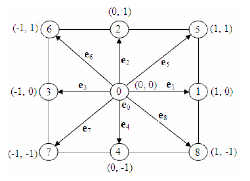
LBM based on different lattice models, depending on the problem, for fluid flow simulation (Guo, (2008)). But the most commonly used model for two-dimensional (2-D) flow problems is the two-dimensional nine-velocity-particles model (D2Q9). In present study, we also used D2Q9 model. Where, eight particles are moving along their axis and diagonally and one is rest particle (Figure 1).
Statement of problem and boundary conditions
The schematic configuration of flow past over two square rods of same sizes D = 20 in staggered arrangement detached with rectangular control rod of size d= 10 is shown in Figure 2 The flow is two dimensional and steady. The height and length of channel of channel are selected as L and H, respectively. Lu = 7.5d, is representing the upstream length from entrance position to the square rods and Ld = 30d is the downstream length from control rod to outlet of channel. The effect of gap spacing between the square rods is studied by taking the values of g = 1, 3 and 6 at different values of Reynolds numbers within the range: Re = 80 – 200 is studied.Since flow is only taken along x direction, so velocity vectors are u=u∞ and v = 0. Since the rods are stationary so, no-slip boundary conditions are used on top and bottom walls of channels as well on the surfaces of rods [15]. The uniform inflow velocity is used at entrance of domain and convective boundary condition is applied at the exit position of channel [32]. The total fluid forces on rectangular rods are calculated using the momentum exchange method [32].
Important parameters
Some important physical parameters are used in this paper which are defined as following
The Reynolds number is defined as
where D is the size of main rod and γ is the kinematic viscosity. The Strouhal number, drag coefficient, lift coefficient and root-mean-square value of drag and lift coefficients (Cdrms and Clrms) are given as
where Ϗs is the vortex shedding frequency, Ωd and Ωl are the force components in longitudinal and transverse directions, respectively and ᴨ is the total number of time steps. Different values of relaxation parameters on different Reynolds numbers are shown in Table 1.
Effect of computational domain, uniform inflow velocity and code validation study
To study the effect of selected computational domain on numerical simulations, different grid resolutions are employed (Table 2) at g = 1 and Re = 80 has been performed and calculated the values of Cdmean and Cdrms of two selected rods. After that the complete obtained results in terms of Cdmean and Cdrms from all selected cases are compared with each other. The numerical results obtained from case II in comparison with other chosen cases, especially, cases IV and V has a negligible influence on physical parameters. According to this investigation, all simulations are performed with case II in present study.
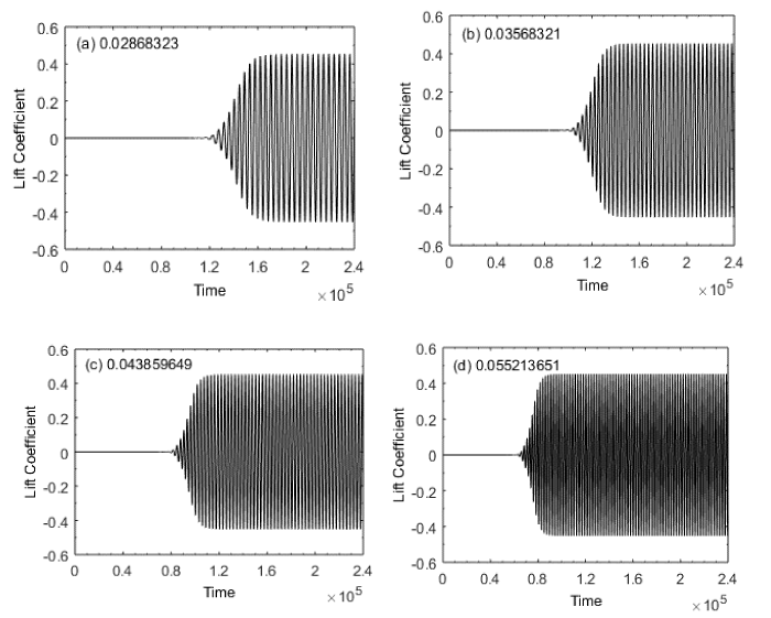
The uniform inflow velocities has great impact in drag reduction and suppression of vortex shedding. Due to uniform inflow velocity, vortex shedding process can be delay or may be faster. Therefore, it is essential to choose an appropriate value of uniform inflow velocity to obtain accurate results. For this, we checked the present code by taking four different values of uniform velocities by taking Reynolds number at Re = 150 and draw the results in terms of lift coefficients. Different values of uniform inflow velocities are chosen as shown in Figure 2(a-d). It is examined that at small values of U∞ = 0.02868323 and U∞ = 0.03568321, much time is required to start periodicity as compared to U∞ = 0.043859649 and U∞ = 0.055213651. At U∞ = 0.55213651, the vortex shedding process much faster that could be influenced on flow characteristics and physical parameters. Therefore, we selected the U∞ = 0.043859649 to get an accurate results in a suitable computational time
In order to check the validity of present code, we have calculated the values of Cdmean and St for flow past a single square rod at Re = 100, 150 and 200 and compared our results with already existing available numerical or experimental data in literature (Table 3). The obtained value of Cdmean at Re = 100 and 150 showing close agreement with values of De and Dalal [33], Gera, et al. [34]. Similarly, the values of Cdmean obtained at Re = 200 from present result is most approximately similar value of Cdmean obtained from the results of Okajima [35], Gera, et al. [34] and Norberg [36]. In this way the values of Strouhal number at Re = 100, 150 and 200, obtained present results having close agreement with results obtained from data of Norberg [36], Davis and Moore [37] and Robichuax, et al. [38].
Results and Discussions
In this section, the effect of gap spacing (g = 1, 3 & 6) between the rods and Reynolds number (Re = 80 - 200) on flow structure mechanism is discussed for flow past over two square rods in staggered configuration. The results are obtained in terms of vorticity visualization, power spectrum analysis of lift coefficients and force statistics. It is important to state here that in vorticity contour visualization graphs the solid lines represent the positive vortices generated from the lower corner and dashed lines represent the negative vortices generated from the upper corner of the rods. To avoid repetition only some important representative plots will be shown in this paper. Since the rapid buildup of vortex shedding define the phenomena of oscillation. The oscillating flow mechanism is described by Strouhal number which is calculated by applying the Fast Fourier Transform (FFT) on lift coefficients data. The highest peak in each spectrum graph is termed as primary vortex shedding frequency (PVSF). These PVSF give the value of Strouhal number for each case. The other peaks in the spectrum graphs are termed as secondary rod interaction frequencies (SRIF). Three distinct flow regimes are observed in this numerical investigation. In the subsections below, we will discuss these flow regimes in details at different Reynolds numbers and gap spacing.
Irregular Single Bluff Body Flow Regime (ISBB)
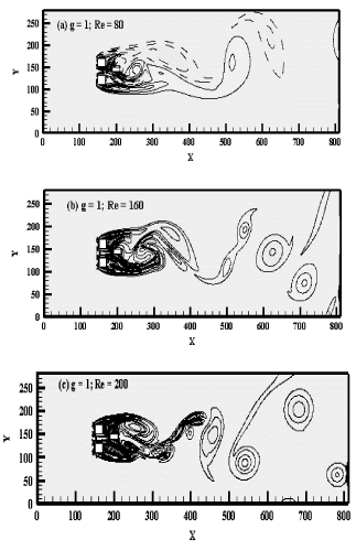
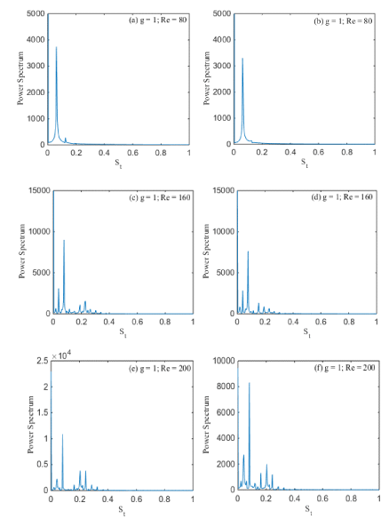
The first flow regime is observed in current study is Irregular Single Bluff Body (ISBB) flow regime. This flow regime is observed at g = 1 and Re = 80-200. Due to small gap spacing between two rods, the shed vortices from the edges of rods are attached with each other, these shed vortices are then suppressed by the control rod placed at some distance to the rods as shown in Figure 3(a-c). Here the negative vortex is examined at (g, Re) = (1, 80), only behind the upper rod and positive vortex behind the lower rod. It is also noticed that modes frequently varies its direction and an irregular shape is formed. For all selected Reynolds number, all the vortices are not round in shape. The generation of narrow and wide wake has been observed in the downstream direction of the computational domain. The flow behind the rod is deflected into one narrow and wide wake. There is no flow in the gap between the rods due to small gap spacing. The flow on the rear side of rods reattached to the front edge of control rod without merging with each other and move towards downstream forming large vortices. This flow regime occurs because of the smaller spacing ratio leads to much weaker gap flows between the two square rods. With the increase in Reynolds number from 80 to 200, the vortices shape on the rear side of bluff body is elongated and the flow become inconsistent. The flow regime of vortices is less regular. The power spectrum analysis of lift coefficient for two square rods detach with the control rod shows that primary vortex shedding frequency for small value of Reynolds number in Figure 4(a, b), while for large value of Reynolds number, the power spectrum analysis of lift coefficient shows primary as well secondary rods interaction frequencies as described in Figure 4(c-f). The magnitude of power spectrum analysis of lift coefficient is also increase with increment in value of Reynolds number.
Flip Flopping flow regime (FF)
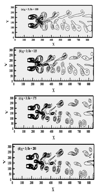
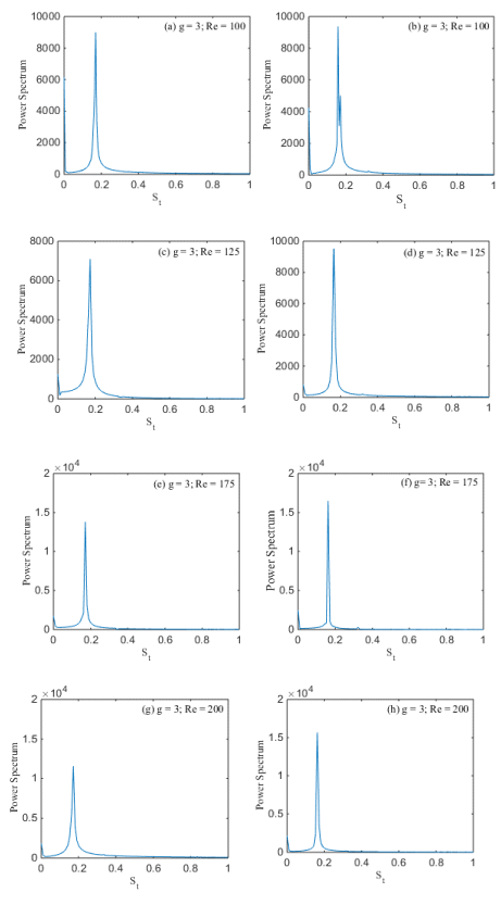
The Flip flopping (FF) flow regime is observed at g = 3 and Re = 80-200. A representative case of this flow regime is shown in Figure 5(a-d). The vortices are generated behind the rods, the strong interaction of flow with rods as well as with the control rod can be observed. The vortices in the downstream are showing merging behavior for small distance. For small values of Reynolds number (Re = 100) the wake generated on the far side of downstream is very weak and is showing irregular behavior (Figure 5(a)). Regularity in the wakes generation occurs with the increase in the value of Reynolds number. At high Reynolds number the generated wakes are fully developed at the exit of computational domain. The shed vortices from the edges of rods after suppressing by control rod move above and below the central line. At small Reynolds number, the shed vortices are longer and are not in regular shape, also lesser in number. But at high Reynolds number, they attain nearly round shape and increase in number. Therefore the wake structure also affected by the Reynolds number as shown in Figure 5(a-d). It is also noticed that mode is seemed to be separated between the rods before attaching with the control rod and both the rods are produced by their own vortices. By increasing the gap spacing, no merging and distortion occurs in the computational domain. The power spectrum of lift coefficient for Flip flopping flow regime is found in Figure 6(a-h) for two square rods detached with the control rod at (Re, g) = (100, 3), (125, 3), (175, 3) and (200, 3) with no multi peaks. It is also notified that power spectrum at g = 3, Re = 100, 125, 175, 200 provided the single sharp peak called primary peak. The rod R2 containing maximum magnitude than the Rod R1. The magnitude of power spectrum analysis is also increases with increase in Re (Figure 6(g, h)).
Anti-Phase Synchronized Flow Regime
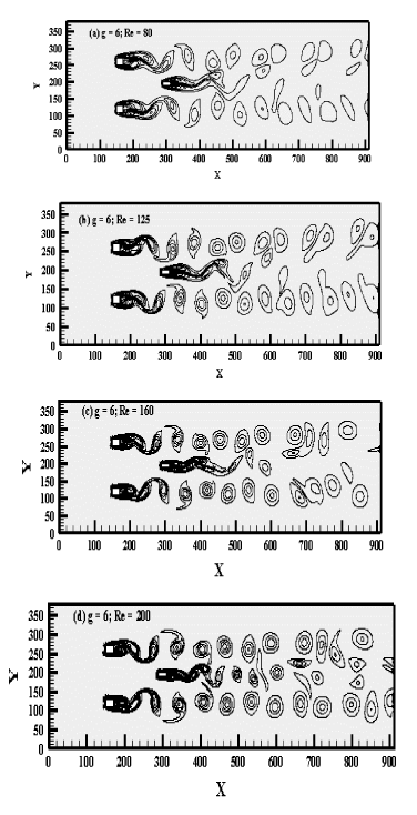
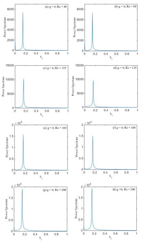
The Anti-Phase Synchronized flow regime is observed at g = 6 with Re = 80-200. The interaction between the wakes is weak because of large gap spacing. The behavior of the wakes in the downstream is almost similar to that of isolated rod wake. There is no distortion in the downstream among wakes. For small value of Re = 80, the behavior of the flow for the two rods is Anti-Phase, while the flow behavior behind control rod is almost steady. Here vortices of both rods did not affect each other and move in stream wise parallel to each other in the downstream of the channel. It is clearly seen in Figure 7(a-d), the vortices after shedding from the edges of rods don’t suppressed or attached with the control rod to a larger extent. The strength of adjoining the vortices increases with the Reynolds number. They move initially without merging and distortion and then spread largely. It is clearly observed in Figure 7(a-d) at initial stage, the shed vortices are round and are representing some irregularity in shape, but remains distinct in downstream of rods. Islam et al., (2012) also examined the same mode behavior on the flow past four square rods in an inline square configuration for distinct gap spacing. Figure 8(a-h) shows that single peak has been observed in the power spectrum analysis of the lift coefficients for all values of Reynolds number which confirms that there is no distortion of vortices in the downstream of channel. Power spectrum at (Re, g) = (80, 6), (125, 6), (160, 6) and (200, 6) for Anti-Phase Synchronized flow regime described the single peak in Figure 8(a-h). The smallest amplitude is observed at (g, Re) = (6, 80) for second rod. The largest amplitude is obtained at (g, Re) = (6, 200) for second rod. It means that by increasing the Reynolds number affects the amplitude as shown in Table 4, Figure 8(a-h).
Force statistics
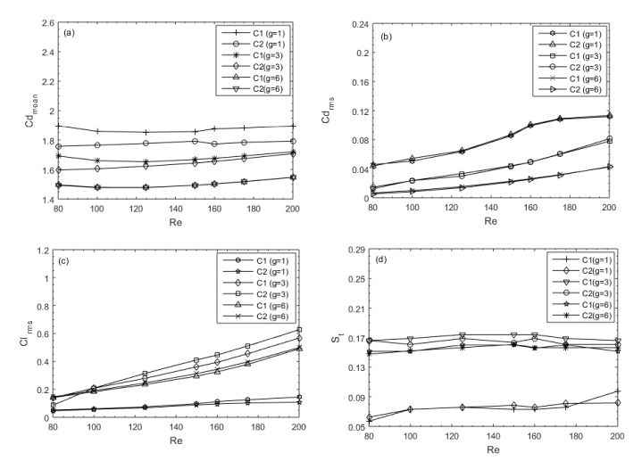
The variation of aerodynamic force coefficients with gap spacing, g = 1, 3 & 6 at Re = 80-200 is presented in Figure 6(a-d). In aerodynamic force coefficients, we computed the values of mean drag coefficients (Cdmean), root mean square of drag coefficients (Cdrms), root mean square of lift coefficients (Clrms), and Strouhal number (St). Firstly Figure 6(a) is representing the values of mean drag coefficient for two square rods detached with control rod. The values of Cdmean for rod R1 with gap spacing g = 1 is representing the mixed trend by increasing the Reynolds number from Re = 80 – 200. Whereas, The values of Cdmean for rod R2 with gap spacing g = 1 showing the increasing behavior from Re = 80 – 200. The maximum value of Cdmean is obtained at (g, Re) = (1, 80) that is 1.8971 for rod R1 as compared to rod R2 at g = 1. Where existing flow regime is the Irregular Single Bluff Body (ISBB) flow regime. The value of Cdmean for rod R1 with g = 3 is expressing the decreasing style from Re = 80 – 125 and then increasing style from Re = 150 – 200. But at g = 3, the value of mean drag coefficients for rod R2 is increasing continually with increment in values of Re. The largest value of Cdmean at g = 3, is obtained again for rod R1 at Re = 200 that is 1.7205. At g = 6, Cdmean values for both selected rods, first decrease from Re = 80 – 125, and then increase in value may be seemed from Re = 150 – 200.
The root mean square values of drag coefficients (Cdrms) for two square rods detached with control rod are shown in Figure 6(b) from Re = 80 – 200 and g = 1, 3 and 6. The Cdrms values for the first and second rod, at g = 1, 3 and 6, are expressing the increasing behavior from Re = 80 – 200. The largest value of Cdrms is obtained for second rod R2 with (g, Re) = (1, 200) that is 0.1135, where the flow mode is Irregular Single Bluff Body (ISBB) flow regime. Similarly, the root mean square values of lift coefficients (Clrms), for both the square rods are increasing with increment in range of Reynolds number from Re = 80 – 200 (Figure 6(c)). The maximum value of Clrms is obtained for rod R1 as compared to rod R2 at g = 1 with Re = 200 i-e 0.1443, where the existing flow mode is Irregular Single Bluff Body (ISBB) flow regime.
The values of Strouhal number (St) for two equal sized square rods detached with horizontal control rod is shown in Figure 6(d). The St values for R1 with g = 1 is showing the increasing behavior from Re = 80 – 200. The point is to be noted, that at Re = 125, 150 and 160, St shows the same value that is 0.0731. For second rod R2 at gap spacing g = 1, St is expressing the mixed trend that is increasing and decreasing from Re = 80 – 200. Here we compare St of both the rods, it is observed that largest value of St is obtained of first rod R1 at (g, Re) = (1, 200) that is 0.0975, where existing flow regime is Irregular Single Bluff Body (ISBB) flow regime. Now if we increase the gap spacing from g = 1 to 3 and 6, the value of St for both the rods, is representing the mixed trend from Re = 80 – 200. The maximum value of St is obtained for second rod R2 with g = 6 and Re = 150, that is 0.1742 as shown in Figure 6(d), where existing flow regime is Anti-Phase Synchronized (APS) flow regime. All calculated values of physical parameters, are also shown in Figure 9 Table 5.
Conclusions
The present numerical study represented the analysis of flow behavior past over two square rods of equal sizes (D = 20) detached with horizontal control rod in staggered configuration. Flow is simulated using the Single Relaxation-Time Lattice Boltzmann Method (SRT-LBM). This study is conducted basically to reduce the fluid forces and to suppress the vortex shedding through passive control method under the effect of gap spacing between the rods and Reynolds number. The gap spacing between the rods are taken as g = 1, 3 and 6, where the Reynolds number is selected within the range of Re = 80 – 200.
Firstly, the effect of computational domain, code validation and grid independence study are discussed. After that, effect of gap spacings (g = 1, 3 and 6) and Reynolds number (Re = 80 – 200) for different flow regimes are analyzed in detail.
Three different types of flow regimes are obtained that are (i) Irregular Single Bluff Body flow regime, (ii) Flip Flopping flow regime and (iii) Anti-Phase Synchronized flow regime.
The chaotic behavior of flow is seemed to be observed at small range of Reynolds number with gap spacing g = 3, but by increasing the range of Re, no merging and distortion of vortices are examined.
The mean drag coefficient of rod R1 is greater than the Cdmean of rod R2 for all three selected gap spacing. It is also representing increasing and decreasing behavior with increment in value of Reynolds number.
The maximum value of mean drag coefficient is attained for first rod R1 at (g, Re) = (1, 80) that is 1.8971 as compared to R2, where existing flow regime is the Irregular Single Bluff Body (ISBB) flow regime.
The values of Strouhal number at g = 1 for both the rods are less than the values of St at g = 3 and 6 for rod R1 and R2. The largest value of St is examined for first rod R1 at (g, Re) = (3, 125), (3, 150), (3, 160), that is 0.1742 as compared to rod R2.
- Fransson JHM, Konieczny P, Alfredsson PH (2004) Flow around a porous rod subject to continuous suction or blowing. Journal of Fluids and Structures 19: 1031-1048. Link: https://bit.ly/3i7TgzJ
- Fujisawa N, Asano Y, Arakawa C, Hashimoto T (2005) Computational and experimental study on flow around a rotationally oscillating circular rod in a uniform flow. Journal of Wind Engineering and Industrial Aerodynamics 93: 137-153. Link: https://bit.ly/3vKCFpE
- Darekar RM, Sherwin SJ (2001) Flow past a bluff body with a wavy stagnation face. Journal of Fluids and Structure 15: 587-596. Link: https://bit.ly/3ib3Ea8
- Williamson CHK (1985) Evolution of a single wake behind a pair of bluff bodies. Journal of Fluid Mechanics 159: 1-18. Link: https://bit.ly/3g2Hy6T
- Kawamura T, Takami H, Kuwahara K (1986) Computation of high Reynolds number flow around a circular rod with surface roughness. Fluid Dynamics Research 1: 145. Link: https://bit.ly/3pnZayB
- Zdravkovich MM (1987) The effect of interference between circular rods in cross flow. Journal of Fluids and Structures 1: 239-261. Link: https://bit.ly/34AsV5A
- Mansingh V, Oosthuizen PH (1990) Effects of splitter plates on the wake flow behind a bluff body. AIAA Journal 28: 778-783. Link: https://bit.ly/2TAgkgt
- Park WC, Higuchi H (1998) Numerical investigation of wake flow control by a splitter plate. KSME International Journal 12: 123-131. Link: https://bit.ly/3yTRTe0
- Alam MM, Moriya M, Takai K, Sakamoto H (2002) Suppression of fluid forces acting on two square Prisms in a tandem arrangement by passive control of flow. Journal of Fluids and Structures 16: 1073-1092. Link: https://bit.ly/3iare6X
- Texier A, Bustamante ASC, David L (2002) Contribution of a short separating plate on the control of the swirling process downstream a half-rod. Experimental Thermal and Fluid Science 26: 565-572.
- Dutta S, Panigrahi PK, Muralidha K (2004) Effect of orientation on the wake of a square rod at low Reynolds numbers. Indian Journal of Engineering and Metrological Sciences 11: 447-459. Link: https://bit.ly/3caGzAA
- Zhou L, Cheng M, Hung KC (2005) Suppression of fluid force on a square rod by flow control. Journal of Fluid and Structures 21: 51-167. Link: https://bit.ly/2RcB9O6
- Agrawal A, Djenidi L, Antonia RA (2006) Investigation of flow around a pair of side-by-side square rods using the Lattice Boltzmann Method. Computers & Fluids 35: 1093-1107. Link: https://bit.ly/3fHogVJ
- Shao C, Wang J (2007) Control of mean and fluctuating forces on a circular rod at high Reynolds numbers. Acta Mechanica Sinica 23: 133-143. Link: https://bit.ly/2SOQl4q
- Guo Z, Liu H, Luo LS, Xu K (2008) A comparative study of the LBE and GKS methods for 2D near incompressible laminar flows. Journal of Computational Physics 227: 4955-4976. Link: https://bit.ly/2S2AmzM
- Turki S (2008) Numerical simulation of passive control on vortex shedding behind square rod using splitter plate. Engineering Applications of Computational Fluid Mechanics 2: 514-524. Link: https://bit.ly/3yY020S
- Vikram CK, Gowda YK, Ravindra HV, Gowda CG (2011) Numerical simulation of two dimensional unsteady flow past two square rods. International Journal of Technology Engineering System 2: 355-360. Link: https://bit.ly/2S6Jd3g
- Yen SC, Liu JH (2011) Wake flow behind two side-by-side square rods. International Journal of Heat and Fluid Flow 32: 41-51. Link: https://bit.ly/2S2Aq2u
- Ali MSM, Doolan CJ, Wheatley V (2011) Low Reynolds number flow over a square rod with a splitter plate. Physics of Fluids 23: 033602. Link: https://bit.ly/3vIiIzV
- Perumal DA, Kumar GV, Dass AK (2012) Numerical simulation of viscous flow over a square rod using Lattice Boltzmann Method. Mathematical Physics. Link: https://bit.ly/3uRjg5r
- Verma PL, Govardhan M (2011) Flow behind bluff bodies in side-by-side arrangement. Journal of Engineering Science and Technology 6: 745-768. Link: https://bit.ly/3vKla98
- Islam SUl, Abbasi WS, Rahman H (2014) Force statistics and wake structure mechanism of flow around a square rod at low Reynolds numbers. International Journal of Mechanical, Aerospace, Industrial and Mechatronics Engineering 8: 1417-1423.
- Golani R, Dhiman AK (2014) Fluid flow and heat transfer across a circular rod in the unsteady flow regime. International Journal of Engineering Science 3: 8-19. Link: https://bit.ly/3fHocVQ
- Ma Y, Rashidi MM, Yang ZG (2019) Numerical simulation of flow past a square rod with a circular bar upstream and a splitter plate downstream. Journal of Hydrodynamics 31: 949-964. Link: https://bit.ly/2S1QT73
- Chauhan MK, Dutta S, More BS, Gandhi BK (2018) Experimental investigation of flow over a square rod with an attached splitter plate at intermediate Reynolds number. Journal of Fluids and Structures 76: 319-335. Link: https://bit.ly/3wOEpyn
- Nemati M, Abady ARSN, Toghraie D, Karimipour A (2018) Numerical investigation of the pseudo-potential lattice Boltzmann modeling of liquid–vapor for multi-phase flows. Physica A: Statistical Mechanics and its Applications 489: 65-77. Link: https://bit.ly/3wNPqzY
- Jourabian M, Darzi AAR, Toghraie D, Ali Akbari O (2018) Melting process in porous media around two hot cylinders: Numerical study using the lattice Boltzmann method. Physica A: Statistical Mechanics and its Applications 509: 316-335. Link: https://bit.ly/3vKxmXh
- Balootaki AA, Karimipour A, Toghraie D (2018) Nano scale lattice Boltzmann method to simulate the mixed convection heat transfer of air in a lid-driven cavity with an endothermic obstacle inside. Physica A: Statistical Mechanics and Its Applications 508: 681-701. Link: https://bit.ly/3g6oAMP
- Mohammad AA (2011) Lattice Boltzmann Method: Fundamentals and Engineering Applications with Computer Codes. Springer. Link: https://bit.ly/3uCQeGx
- Chen S, Doolen GD (1998) Lattice Boltzmann method for fluid flows. Annual Review of Fluid Mechanics 30: 329-364. Link: https://bit.ly/3iboMNA
- Wolf-Gladrow A (2005) Lattice-Gas Cellular Automata and Lattice Boltzmann Models-An introduction, Springer. Link: https://bit.ly/3yVhFi5
- Dazhi Y, Renwei ML, Luo LS, Wei S (2003) Viscous flow computations with the method of lattice Boltzmann equation. Progress in Aerospace Sciences 39: 329-367. Link: https://bit.ly/3caqefb
- De AK, Dalal A (2006) Numerical simulation of unconfined flow past a triangular rod. International Journal for Numerical Methods in Fluids 52: 801-821. Link: https://bit.ly/3uKnzPL
- Gera B, Sharma PK, Singh RK (2010) CFD analysis of 2D unsteady flow around a square rod. International Journal of Applied Engineering Research 1: 602-610. Link: https://bit.ly/3uFHmj9
- Okajima (1982) Strouhal numbers of rectangular rods. Journal of Fluid Mechanics 123: 379-398. Link: https://bit.ly/3wUyOXt
- Norberg C (1993) Flow around rectangular rods: Pressure forces and wake frequencies. Journal of Wind Engineering and Industrial Aerodynamics 49: 187-196. Link: https://bit.ly/3uKo1NX
- Davis RWM, Moore EF (1982) A numerical study of vortex shedding from rectangles. Journal of Fluid Mechanics 116: 475-506. Link: https://bit.ly/3fJMwXs
- Robichuax J, Balachandar S, Vanka SP (1999) Three-dimensional floquet instability of the wake of a square rod. Physics of Fluids 11: 560-578. Link: https://bit.ly/3wPL7UJ
- Dutta S, Oanigrahi PK, Muralidhar K (2008) Effect of orientation on the wake of a square rod at low Reynolds numbers. Journal of Engineering Mechanics 134: 447-459.
Article Alerts
Subscribe to our articles alerts and stay tuned.
 This work is licensed under a Creative Commons Attribution 4.0 International License.
 Help ?

PTZ: We're glad you're here. Please click "create a new query" if you are a new visitor to our website and need further information from us.
If you are already a member of our network and need to keep track of any developments regarding a question you have already submitted, click "take me to my Query."

 Save to Mendeley