Annals of Mathematics and Physics
An innovative method and a medical screening device for cancer detection in real-time
K Papageorgiou1* and G Papageorgiou2
2University of Medicine and Pharmacy of Craiova, Faculty of Medicine, Romania
Cite this as
Papageorgiou K, Papageorgiou G (2023) An innovative method and a medical screening device for cancer detection in real-time. Ann Math Phys 6(1): 083-088. DOI: 10.17352/amp.000084Copyright Licence
© 2023 Papageorgiou K, et al. This is an open-access article distributed under the terms of the Creative Commons Attribution License, which permits unrestricted use, distribution, and reproduction in any medium, provided the original author and source are credited.Histopathology is the main technique to assess the presence of cancer cells in biopsy material and for the evaluation of positive resection margins, but it is not real-time. Older methods to assess resection margin intraoperatively are either time-consuming or exhibit a low accuracy. More recent imaging techniques have various drawbacks, like the need for exogenous contrast agents or excessive time to assess the entire resection surface or a low diagnostic performance in detecting certain types of cancer. The purpose of the current research work is the development of a medical screening device for cancer cells detection with very high accuracy and selectivity, based on a newly developed method in order to experimentally measure in real-time the excitation response of the charged elements of the biological tissue under study to the applied alternative electrical field, over a wide range of frequency spectra.
The aim of this study is to present an innovative method and results from a prototype medical screening device, which allows the selective and “real-time” detection of cancer cells of any type among normal cells in any tissue type.
The innovation of the proposed method lies in the view of the cell membrane emulation as an electrical circuit and also in the ability to experimentally measure in real-time the excitation response of the charged elements of the biological tissue under studies like ions, interfaces or dipoles to the applied alternative electrical field, over a wide range of frequency spectra according to the dielectric spectroscopy method. The ions can very easily follow the variations of the applied alternating electric field moving along the dynamic lines of the field. In contrast, the incapability of the abnormal neoplastic cellular formations to follow the frequency changes causes them to perform dipole oscillation instead of moving along the dynamic lines of the field. This experimentally appears as a significant increase of the capacitive component contribution to the total impedance of the tissue, relative to the purely electrical resistance contribution of the ions. A model, backed by the relevant mathematical equations, has been developed to integrate the unknown impedance of both the tissue under assessment and the interdigital micro-sensor with the known complex impedance of the data acquisition system. The ability to selectively detect cancer cells has an obvious interest and various applications in cancer diagnosis and therapy.
Introduction
Despite the significant and continuous scientific progress made, cancer is the second leading cause of death globally and is responsible for an estimated 9.6 million deaths in 2018; globally, about one in six deaths is due to cancer currently and cancer incidence is expected to grow from 18.1 million in 2018 to 29.5 million in 2030 [1]. Early cancer diagnosis and treatment can significantly reduce mortality and can potentially lead to a cure in some of the most common cancer types, such as breast, cervical, oral, or colorectal cancer. However, screening tests such as liquid biopsies [2-8] for the detection of circulating tumor cells, DNA, or other cancer biomarkers are still facing significant challenges such as limited sensitivity and specificity, which also increase the risk of overdiagnosis [9]. Surgical resection, when feasible, is one of the most successful modalities in significantly prolonging the survival of patients with solid cancers. It was estimated that by 2030, 45 million cancer surgery procedures will be performed annually worldwide, which is more than triple the number of cancer surgery procedures estimated in 2015 [10]. The ability to accurately distinguish between normal and cancer cells is critical for the definition of the resection margin and eventually for the success of the therapy [11]. Yet, the evaluation of positive resection margins is currently performed by histopathology [12-16] after surgery and typically requires several days. Methods allowing intraoperative resection margin assessment have therefore been developed, such as frozen section analysis, touch preparation cytology, intraoperative ultrasound, and specimen radiography. However, these methods are either time-consuming or exhibit a low accuracy, which negatively impacts complete tumor removal during cancer surgery, in particular when the tumor is in or close to functionally important areas (brain and kidney surgery or close to large blood vessels), or in areas for which the extent of surgery must be minimized due to aesthetic concerns (squamous cell carcinoma or melanoma of the face). Other more recent techniques include spectroscopy (fluorescent spectroscopy, diffuse reflectance spectroscopy, mass spectrometry, Raman spectroscopy, Cerenkov luminescence imaging, hyperspectral imaging), endoscopy (high-resolution micro-endoscopy, narrow band imaging), and other imaging techniques (optical coherence tomography, ultrasound, fluorescence-labeled antibodies, immunoblotting) occasionally assisted by augmented reality methodologies. Despite the potential of these techniques, they have various drawbacks, like the need for exogenous contrast agents or excessive time to assess the entire resection surface, or low diagnostic performance in detecting certain types of cancer and the evidence of the value added from some of these techniques is scarce at this point in time [17].
The innovative method
The novel innovative method described in the current paper is addressing not only the need to detect cancerous cells with the highest sensitivity and selectivity but also the need to do so intraoperatively and in “real-time”. More specifically, the innovation of the proposed method [18] lies in the view of the cell membrane emulation as an electrical circuit and also in the ability to experimentally measure in real-time the excitation response of the charged elements of the biological tissue under study (ions, interfaces or dipoles) to the applied alternative electrical field, over a wide range of frequency spectra according to the dielectric spectroscopy method.
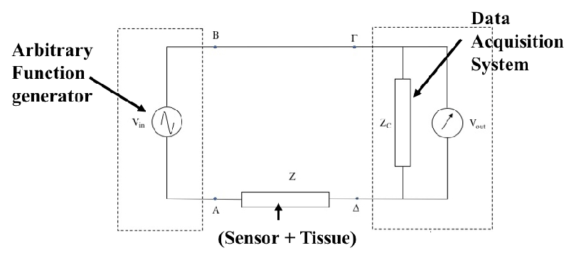
A model, backed by the relevant mathematical equations, has been developed to calculate the capacitive reactance and also to integrate the (unknown) impedance of the tissue under assessment using an interdigital micro-sensor with the (known) complex impedance of a data acquisition system as shown in the schematic in Figure 1.
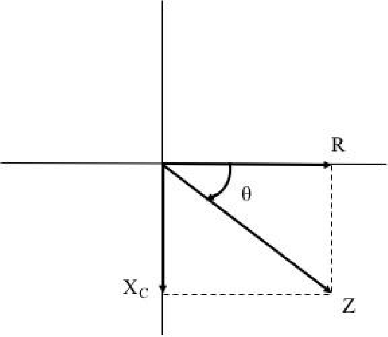
More specifically, Kirchhoff’s first law on the closed loop of the electric circuit of Figure 2 gives for the unknown steady-state impedance Z (s = jω):
Therefore, the unknown steady-state impedance Z (s = jω) will be given by the relation:
Where the quantities Vin (jω) and Vout (jω) represent the discrete Fourier transforms of the excitation and response signals of the circuit respectively. From the last relation, it is obvious that the calculation of the unknown tissue impedance is experimentally feasible with the appropriate measurement of the excitation and response voltages Vin (jω) and Vout (jω) respectively of a data acquisition device with known impedance ZC
Furthermore, writing the above expression (1) as
And taking into account that the quantity Vout (jω) / Vin (jω) by definition represents the transfer function G (jω), the previous relation (2) results in as follows
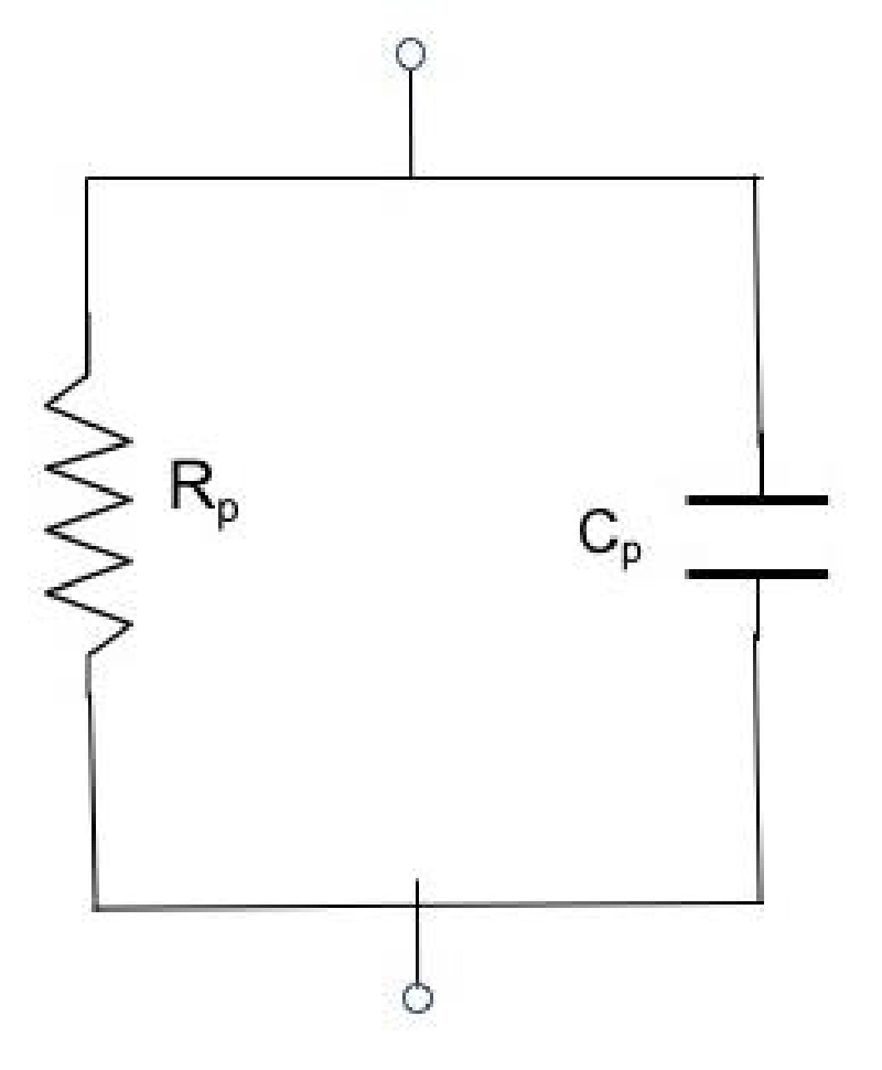
From the above relation (3), it becomes clear that by measuring the excitation and response voltages with the help of a data acquisition device with known complex impedance ZC(jω), the unknown steady-state impedance Z(jω) can be calculated. Then, having measured the steady-state impedance Z(jω) of the unknown element, the resistance Rp and capacitance Cp values of the equivalent RC circuit (Rp//Cp) which simulates both the sensor and the testing material (Figure 3), can be calculated.
From this circuit, because Rp//Cp we can write the expression:
Therefore:
Taking into account that the complex conductivity (Y) is defined as
The conductivity (G) as
And susceptibility (B) as
Where
From equation (4) it is obvious that the relationship
Can be re-written as:
Y = G + jB (10)
From which it is obvious that:
G = Re{Y} (11)
Therefore,
Additionally
B = Im{Y} (13)
Therefore, equation (13) using equations (7) and (8) becomes
Therefore, having measured according to the proposed methodology, the value of the unknown impedance of the tissue in question as well as the value of the electrical resistance of the equivalent RC circuit, we can calculate the value of the angle θ that forms the total impedance vector with respect to the electrical resistance Rp from the following relations
(15) or (16)
Where Z = sqrt (Ri2 + Xc2) (17)
As emerges from Figure 2, where the phasor of the pure electrical resistance contribution is depicted in the horizontal axis while the phasor of the pure capacitance reactance contribution to the total impedance vector Z is depicted in the vertical axis.
The prototype medical device
A prototype medical device has been created and used to demonstrate its performance in a real clinical setting of brain surgery to detect and excise tumor tissue and the collected data have been included in a patent application [18]. The screening medical device consists of four distinct parts: a flat dielectric sensor, an electronic system for wireless or wired data transmission, a data acquisition and processing system, and a computer (PC) for software execution. Dielectric sensors are the most flexible form of interdigital sensors with a wide range of applications. They are essentially flat single-sided capacitors forming a fringing electrical field over their surface and offering the potential of non-destructive and non-invasive testing of the materials as they are in close contact with them on one side. The interdigital micro-sensor consists of a repeating pattern of coplanar capacitors on a non-porous thin film substrate as shown in Figure 4.
The dynamic lines of the fringing electrical field created by the coplanar electrodes penetrate the tissue under test, which is now constituting the dielectric material of the flat capacitor at a depth that is determined by the relative distance between the electrodes and their width. In this way, the choice of sensor defines the representative volume that is interrogated with the method. The sensor is interrogated by a dielectric spectroscopy unit and an impedance spectrum is obtained at regular time intervals and in real-time, as a response of the tissues to the applied alternative electrical field frequency.
The application of the flat interdigital sensors allows for the in-process monitoring of the dispersion of cancerous cells in the biological tissue, as the transformation from the parallel plate capacitor to coplanar electrodes. When the electric field is interacting with the dielectric material, contributions from the polarization of dipoles and ionic species take place in the vicinity of the capacitor plates or at randomly existing cancer cells acting as interfaces in the material volume. Consequently, the increase of the capacitive contribution to the total impedance of the tissue signifies directly the existence of cancerous cells in the area under assessment.
Impedance measurements were performed using a prototype screening device with an advanced electronic Data Acquisition and dielectric analysis system from National Instruments (NI USB X-series, Mod. NI USB- 6356) and commercially available micro-sensors (dielectric sensors from Gel Instrumente AG, Oberuzwil, Switzerland). The amplitude of the excitation alternative voltage applied to the sensors was 10V. A sweep of 12 frequencies between 10 Hz and 100 kHz was made. The commercial dielectric sensor used comprises an assembly of interdigital copper electrodes, printed with a spacing of 300 μm on a polymeric film.
The electronic data acquisition system, NI USB-6356 used for this application has 8 simultaneous analog inputs, a sampling frequency of at least 1.25MS/s/channel with 16-bit resolution, timing resolution of 10ns, memory of at least 32MS to ensure complete data acquisition cycles even with high data flow rates through a single serial bus port, 24 digital I/O lines and 32 bit counter/timer.
A prototype of the medical device has been created and used to demonstrate its performance in a real clinical setting of brain surgery to detect and excise tumor tissue.
For tumors of the central nervous system and sheaths, the state-of-the-art level of technique for the correct identification of the boundaries is based mainly on the experience of the neurosurgeon and the help provided to him in this direction, by all the technical means developed over time and used until today (surgical microscope, neuro-navigation, intraoperative ultrasound). Although this development has improved the available capabilities, it has not eliminated the problem. For example, during surgical intervention in the brain for the exclusion of a neoplastic mass, the loss of cerebrospinal fluid significantly affects the parameters of the neuro-navigation device, resulting in large discrepancies in the finding and safe exclusion of the tumor. This problem is aggravated due to the changes that the gradual exclusion of the neoplastic mass causes at the same time in the topography of the area (change in the volume of the brain, displacement of the brain). Therefore, the requirement for accurate delineation of a neoplastic tumor for the successful outcome of surgical intervention on the patient remains and ultimately relies to a large extent on the skills and experience of the surgeon.
Additionally, due to the fact that in malignant brain tumors, malignant cells often infiltrate widely into normal tissue and also taking into account the histological differentiation of the tumor within its mass itself, in many cases results that the tumor margins can be different from those determined by macroscopic findings or the imaging techniques. It is emphasized that the distinction between normal and neoplastic tissue intraoperatively using the proposed innovative method, ensures the safe total exclusion of the tumor, preventing the exclusion of surrounding healthy nerve tissue, resulting in the manifestation of neurological deficit symptoms for the patient.
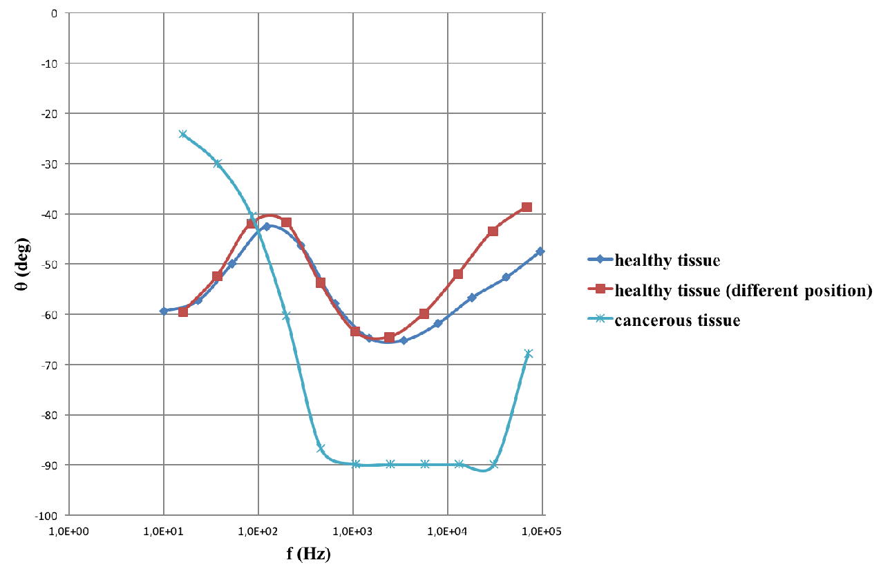
The data shown in the impedance spectrum of Figure 5, are acquired with the help of the prototype medical device using a dielectric sensor of thin film substrate type. The graph depicts the angle θ which the phasor of the pure capacitance reactance forms with the total impedance of the tissue under examination as a function of the scanning frequency. The red and dark blue lines depict the impendence spectra acquired from healthy tissue in different positions. The light blue curve represents the impendence spectra data acquired from a cancerous tissue which exhibits a very characteristic and almost pure capacitance behaviour that appears as a horizontal line parallel to the frequency axis and close to -900.
The data analysis performed so far confirmed a robust clinical Proof-of-Concept (PoC) of the screening device and demonstrate its excellent performance in a real clinical setting of brain surgery to detect and excise tumor tissue.
However in order to support the ability of the medical screening device for tumor detection with a very high accuracy, sensitivity, and specificity, additional data from extensive clinical trials are needed in order to minimize the statistical errors of these crucial parameters. For that reason, two additional clinical studies in the University Hospital of Patras will be conducted: one in patients with skin cancer (BCC, FCC, ...), which has been identified as the first/faster clinical indication to be pursued by the device, and the another in patients with Head and Neck tumor, which has been identified as the second clinical indication to demonstrate additional clinical PoC for the high selectivity of the device. A control sample is also planned to be taken into account in data analysis from those two clinical trials. Further data analysis in order to define a range of operational parameters and provide information for the optimization of the device is also planned.
Conclusion
An innovative method and a prototype screening medical device for selective and real-time cancer detection are presented here. The response of cell impedance to excitation voltage is determined by the mobility of the ions and dipoles present in the tissue of the area under consideration.
The ions follow the frequency variation of the applied alternating electric field as they are moving along the dynamic lines of the field, in contrast with the cancerous formations whose mobility is limited and thus they behave as interfaces that contribute as a dipole oscillation to the complex dielectric permeability. Experimentally this appears as a significant increase in the capacitive component of the tissue impedance, in contrast to the purely electrical resistance contribution of the ions.
Measuring the capacitive resistance or in other words determining the contribution of the purely capacitive component of a biological tissue to its total impedance, indirectly defines the volume of the cell membranes that the alternating current encountering as it penetrates the tissue under investigation during the measurement procedure. Since the cell membrane structure exhibits the shape, characteristics, and behavior of a capacitor when an alternating voltage is applied, we can accurately determine the capacitive resistance contribution of biological tissue under examination to its total impedance, simply by measuring the angle θ formed by the phasor of the capacitive resistance with respect to the phasor of the total impedance which a biological tissue exhibits as a response in the flow of an alternating current.
Future work
An innovative method and preliminary results from a prototype medical screening device, which allows the selective and “real-time” detection of cancer cells are presented here. The effectiveness of the proposed method and the proof of concept of the screening device have been demonstrated and confirmed from the studies performed so far, analysing the data collected from several different cases in a real clinical setting of brain surgery to detect and excise tumor tissue.
The device development strategy is articulated as a series of several distinct steps, each composed of activities aiming to specific, de-risking milestones. The current prototype device will be used to collect data from in-vitro cell lines and human tumor xenograft models, aiming to demonstrate its potential in various types of cancer cells, define a range of operational parameters and provide information for the optimization of the device.
Additionally, two clinical studies will be conducted; one in patients with skin cancer which has been identified as the first and faster clinical indication to be pursued by the device, and the other in patients with tumor in the head and neck area to demonstrate additional clinical proof of concept with the device.
The method’s reliability and accuracy are proven, and it could be widely implemented as an alternative to frozen sections intraoperatively, thus reducing treatment costs and surgical time.
- Bray F, Ferlay J, Soerjomataram I, Siegel RL, Torre LA, Jemal A. Global cancer statistics 2018: GLOBOCAN estimates of incidence and mortality worldwide for 36 cancers in 185 countries. CA Cancer J Clin. 2018 Nov;68(6):394-424. doi: 10.3322/caac.21492. Epub 2018 Sep 12. Erratum in: CA Cancer J Clin. 2020 Jul;70(4):313. PMID: 30207593.
- Cucciniello L, Gerratana L, Puglisi F. Liquid Biopsy, an Everchanging Balance between Clinical Utility and Emerging Technologies. Cancers (Basel). 2022 Sep 1;14(17):4277. doi: 10.3390/cancers14174277. PMID: 36077819; PMCID: PMC9454764.
- Eslami-S Z, Cortés-Hernández LE, Thomas F, Pantel K, Alix-Panabières C. Functional analysis of circulating tumour cells: the KEY to understand the biology of the metastatic cascade. Br J Cancer. 2022 Sep;127(5):800-810. doi: 10.1038/s41416-022-01819-1. Epub 2022 Apr 28. PMID: 35484215; PMCID: PMC9427839.
- Lautert-Dutra W, Dos Reis RB, Squire JA. Precision medicine for prostate cancer-improved outcome prediction for low-intermediate risk disease using a six-gene copy number alteration classifier. Br J Cancer. 2023 Jun;128(12):2163-2164. doi: 10.1038/s41416-023-02289-9. Epub 2023 Apr 29. PMID: 37120668; PMCID: PMC10241778.
- Reduzzi C, Di Cosimo S, Gerratana L, Motta R, Martinetti A, Vingiani A, D'Amico P, Zhang Y, Vismara M, Depretto C, Scaperrotta G, Folli S, Pruneri G, Cristofanilli M, Daidone MG, Cappelletti V. Circulating Tumor Cell Clusters Are Frequently Detected in Women with Early-Stage Breast Cancer. Cancers (Basel). 2021 May 13;13(10):2356. doi: 10.3390/cancers13102356. PMID: 34068368; PMCID: PMC8153325.
- Silvestri M, Reduzzi C, Feliciello G, Vismara M, Schamberger T, Köstler C, Motta R, Calza S, Ferraris C, Vingiani A, Pruneri G, Daidone MG, Klein CA, Polzer B, Cappelletti V. Detection of Genomically Aberrant Cells within Circulating Tumor Microemboli (CTMs) Isolated from Early-Stage Breast Cancer Patients. Cancers (Basel). 2021 Mar 19;13(6):1409. doi: 10.3390/cancers13061409. PMID: 33808748; PMCID: PMC8003526.
- Maass KK, Schad PS, Finster AME, Puranachot P, Rosing F, Wedig T, Schwarz N, Stumpf N, Pfister SM, Pajtler KW. From Sampling to Sequencing: A Liquid Biopsy Pre-Analytic Workflow to Maximize Multi-Layer Genomic Information from a Single Tube. Cancers (Basel). 2021 Jun 15;13(12):3002. doi: 10.3390/cancers13123002. PMID: 34203921; PMCID: PMC8232701.
- Lee HL, Chiou JF, Wang PY, Lu LS, Shen CN, Hsu HL, Burnouf T, Ting LL, Chou PC, Chung CL, Lee KL, Shiah HS, Liu YL, Chen YJ. Ex Vivo Expansion and Drug Sensitivity Profiling of Circulating Tumor Cells from Patients with Small Cell Lung Cancer. Cancers (Basel). 2020 Nov 16;12(11):3394. doi: 10.3390/cancers12113394. PMID: 33207745; PMCID: PMC7696848.
- Schiffman L, Wisenblit J. Consumer behavior. 2015.
- Sullivan R, Alatise OI, Anderson BO, Audisio R, Autier P, Aggarwal A, Balch C, Brennan MF, Dare A, D'Cruz A, Eggermont AM, Fleming K, Gueye SM, Hagander L, Herrera CA, Holmer H, Ilbawi AM, Jarnheimer A, Ji JF, Kingham TP, Liberman J, Leather AJ, Meara JG, Mukhopadhyay S, Murthy SS, Omar S, Parham GP, Pramesh CS, Riviello R, Rodin D, Santini L, Shrikhande SV, Shrime M, Thomas R, Tsunoda AT, van de Velde C, Veronesi U, Vijaykumar DK, Watters D, Wang S, Wu YL, Zeiton M, Purushotham A. Global cancer surgery: delivering safe, affordable, and timely cancer surgery. Lancet Oncol. 2015 Sep;16(11):1193-224. doi: 10.1016/S1470-2045(15)00223-5. PMID: 26427363.
- Tummers L. Public policy and behaviour change. PAR. 2019; 79(6).
- Veta M, Pluim JP, van Diest PJ, Viergever MA. Breast cancer histopathology image analysis: a review. IEEE Trans Biomed Eng. 2014 May;61(5):1400-11. doi: 10.1109/TBME.2014.2303852. Erratum in: IEEE Trans Biomed Eng. 2014 Nov;61(11):2819. PMID: 24759275.
- Humphrey PA. Histopathology of Prostate Cancer CSH (2017). 2017. doi: 10.1101/cshperspect.a030411.
- Coudray N, Ocampo PS, Sakellaropoulos T, Narula N, Snuderl M, Fenyö D, Moreira AL, Razavian N, Tsirigos A. Classification and mutation prediction from non-small cell lung cancer histopathology images using deep learning. Nat Med. 2018 Oct;24(10):1559-1567. doi: 10.1038/s41591-018-0177-5. Epub 2018 Sep 17. PMID: 30224757; PMCID: PMC9847512.
- Hameed Z, Zahia S, Garcia-Zapirain B, Javier Aguirre J, María Vanegas A. Breast Cancer Histopathology Image Classification Using an Ensemble of Deep Learning Models. Sensors (Basel). 2020 Aug 5;20(16):4373. doi: 10.3390/s20164373. PMID: 32764398; PMCID: PMC7472736.
- Belsare AD. Classification of breast cancer histopathology images using texture feature analysis. IEEE Tencon 2015 2015 IEEE Region 10 Conference. DOI: 10.1109/TENCON.2015.7372809
- Fabelo H. In-vivo and ex-vivo tissue analysis through hyperspectral imaging techniques: revealing the invisible features of cancer. Cancers. 2019; 11(6).
- Papageorgiou K. Method and Medical screening device for identification and mapping of neoplastic cells in real time. Patent number: 20180100575/31-12-18
Article Alerts
Subscribe to our articles alerts and stay tuned.
 This work is licensed under a Creative Commons Attribution 4.0 International License.
 Help ?

PTZ: We're glad you're here. Please click "create a new query" if you are a new visitor to our website and need further information from us.
If you are already a member of our network and need to keep track of any developments regarding a question you have already submitted, click "take me to my Query."



 Save to Mendeley